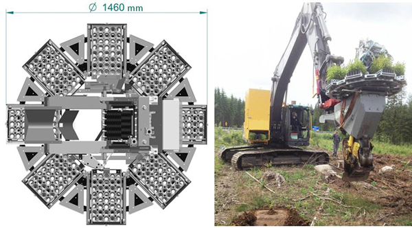
Fig. 1. Top view drawing of the MagMat tray carousel (left) and the test-rig mounted on a Bracke Planter during the field testing (right). Note that the test-rig lacks a protective barrier around the carousel. Photo and drawing: Rikard Wennberg.
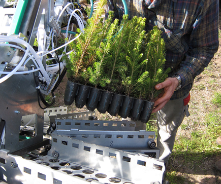
Fig. 2. Loading a Hiko cultivation tray onto one of MagMat’s eight frames. Photo: Rikard Wennberg.
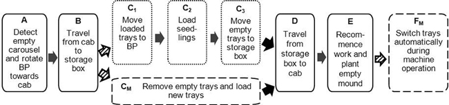
Fig. 3. Flowchart of the work elements involved in reloading the Bracke Planter (BP) with seedlings. Dotted- and dashed-border boxes represent work elements exclusive to the 70Car and MagMat carousels respectively, while elements common to both carousels have a solid border.
| Table 1. Baseline cost factors for the base machine and Bracke Planter planting device. | ||
| Factor | Unit a) | Value |
| Mid-sized tracked excavator | ||
| Purchase price including seedling storage box | Euro | 172 200 |
| Full labour costs including operator travel costs | Euro SMh–1 | 32 |
| Insurance and administration | Euro SMh–1 | 2 |
| Maintenance, lubrication and fuel costs | Euro PWh–1 | 18.5 |
| Scheduled time | SMh yr–1 | 1600 |
| Bracke Planter planting device | ||
| Purchase price | Euro | 55 560 |
| Maintenance costs | Euro PWh–1 | 2.1 |
| Scheduled time | SMh yr–1 | 1200 |
| a) SMh = Scheduled Machine hour; PWh = Productive Work hour; yr = year | ||
| Table 2. Parameter values for the Bracke Planter and M-Planter used in the baseline and sensitivity analysis. | |||||
| Parameter | Unit a) | Baseline value | Sensitivity analysis | ||
| Bracke Planter | M-Planter | Minimum | Maximum | ||
| Mean planting time excluding seedling reloading | s pl–1 | 14.9 b) | 13.0 c) | –40% | +30% |
| Fixed costs (including full labour costs) | Euro SMh–1 | 58.0 | 61.0 | –10% | +40% |
| Variable costs | Euro PWh–1 | 20.5 | 20.8 | –10% | +40% |
| Interest rate | % | 5 | 5 | 3 | 10 |
| Opening/closing protective barrier on MagMat | s reload–1 | 10 | 10 | 0 | 60 |
| Automatic tray switching time | s tray–1 | 25 | 25 | 0 | 60 |
| Mechanical availability (MA) of MagMat | % | 100 | 100 | 80 | 100 |
| a) pl = seedling; SMh = Scheduled Machine hour; PWh = Productive Work hour b) from Ersson et al. (2011) c) based on values from Rantala et al. (2009) | |||||
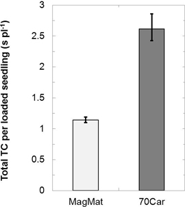
Fig. 4. The mean total time consumption (TC) per loaded seedling for the standard Bracke Planter seedling carousel (70Car) and MagMat tray carousel. MagMat’s TC includes an assumed 10 s per reload for opening/closing a protective barrier. Vertical bars delineate the range of means for the landing time study’s three operators.
| Table 3. Average time consumption (TC) values and ranges per work element when three different operators reloaded seedlings during the time study. | |||
| Work element abbreviation in Fig. 3 | Work element | Mean TC per reload (s) | Range of TC per reload (s) |
| Common elements for both carousels | |||
| A | Detect empty carousel and rotate planting device | 13 | 8–15 |
| B + D | Travelling to and from cab – seedling storage box | 36 | 27–46 |
| E | Recommence work and plant in empty mound | 15 | 14–20 |
| 70Car (70 seedlings per reload) | |||
| C1 + C3 | Moving trays between storage box and carousel | 14 | 9–20 |
| C2 | Seedling reloading | 105 | 94–115 |
| Total for 70Car | 183 | 170–200 | |
| MagMat (320 seedlings per reload) | |||
| CM | Reloading trays including moving trays between storage box and carousel and removing empty trays | 90 a) | 83–99 a) |
| FM | Automatic tray switching during machine operation | 200 | 192–264 |
| Total for MagMat | 354 a) | 303–410 a) | |
| a) Not including an assumed 10 s per reload for opening/closing protective barrier | |||
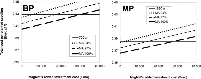
Fig. 5. Total cost per planted seedling of the Bracke Planter (BP) and M-Planter (MP) as a function of the added investment cost for MagMat and its mechanical availability (MA). 70Car and 162Car are the current seedling carousels for the Bracke Planter and M-Planter respectively. Note: the y-axes have been truncated.
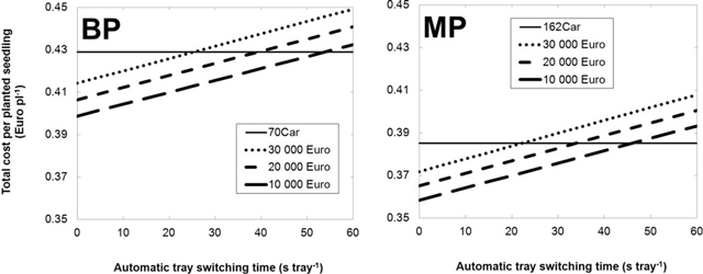
Fig. 6. Total cost per planted seedling of the Bracke Planter (BP) and M-Planter (MP) as a function of how quickly seedling trays can be switched automatically on the MagMat tray carousel and its added investment cost (assuming 100% MA). 70Car and 162Car are the current seedling carousels for the Bracke Planter and M-Planter respectively. Note: the y-axes have been truncated.
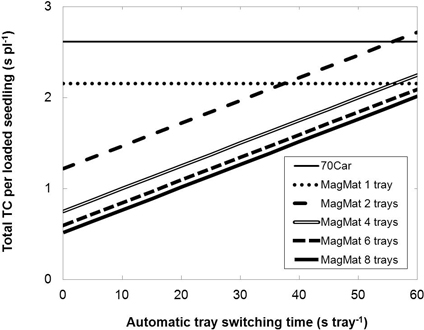
Fig. 7. The time consumption (TC) of various MagMat capacities as a function of how quickly seedling trays can be switched automatically for configurations with more than one tray. Mechanical availability (MA) is assumed to be 100% and that the TC for applicable work elements equal the mean values presented in Table 3.