Tobias Semberg,
Anders Nilsson,
Rolf Björheden,
Linnea Hansson 
Real-time target point identification and automated log grasping by a forwarder, using a single stereo camera for both object detection and boom-tip control
Semberg T., Nilsson A., Björheden R., Hansson L. (2024). Real-time target point identification and automated log grasping by a forwarder, using a single stereo camera for both object detection and boom-tip control. Silva Fennica vol. 58 no. 1 article id 23062. https://doi.org/10.14214/sf.23062
Highlights
- Simple target-point detection in real time using only a stereo camera
- Sturdiness ensured through the simple feedback system based on the same camera
- Automated boom-tip control and log grasping successfully tested on full-sized forwarder
- A step toward semi-automation (operator support) or autonomous forwarding.
Abstract
The forest industry is constantly striving to increase productivity and cut costs, and many research and innovation projects are currently focusing on semi-automated or autonomous systems. A key element, with several possible solutions, is automated log grasping, where researchers and manufacturers are looking for efficient and sturdy ways to solve the task in real-time forwarding operations. This study presents a simple method for automated log grasping using only a single stereo camera for object detection (log and grapple) and a simple controller moving the boom, with feedback from the camera as boom-tip control. The accuracy, precision, and repeatability of the method was tested on a full-scale forwarder. Boom movements were examined from two different start positions in relation to the target position, with the log placed at three different angles. The overall log-grasping success was also evaluated. The tests were performed in a full-scale, real-time operation, without hand-eye calibration or other sensor data from the machine. The method was precise, with high repeatability, but the grasping point showed a minor systematic offset, depending on log angle. However, the deviation in accuracy was too small to affect the success rate. In practice, the most difficult log angles can be avoided by moving the machine slightly. The log grasping method may become part of an autonomous forwarding system or could provide operator support in semi-automated systems.
Keywords
vector analysis;
forwarder;
forest operations;
loading;
boom automation;
object detection;
stereo camera
- Semberg, Skogforsk (The Forestry Research Institute of Sweden), Uppsala Science Park, 751 83 Uppsala, Sweden E-mail tobias.semberg@skogforsk.se
- Nilsson, Skogforsk (The Forestry Research Institute of Sweden), Uppsala Science Park, 751 83 Uppsala, Sweden E-mail anders.nilsson@skogforsk.se
-
Björheden,
Skogforsk (The Forestry Research Institute of Sweden), Uppsala Science Park, 751 83 Uppsala, Sweden
 https://orcid.org/0000-0002-4158-102X
E-mail
rolf.bjorheden@skogforsk.se
https://orcid.org/0000-0002-4158-102X
E-mail
rolf.bjorheden@skogforsk.se
-
Hansson,
Skogforsk (The Forestry Research Institute of Sweden), Uppsala Science Park, 751 83 Uppsala, Sweden
https://orcid.org/0000-0002-9788-1734
E-mail
linnea.hansson@skogforsk.se
Received 23 October 2023 Accepted 7 February 2024 Published 28 February 2024
Views 44992
Available at https://doi.org/10.14214/sf.23062 | Download PDF

Supplementary Files
1 Introduction
The forest industry is constantly striving to increase productivity and cut costs. The wage of a forwarder operator is generally 30–40% of the hourly rate of the forwarding cost (Hellström et al. 2009). In the quest for greater cost efficiency in forestry, new research and innovation projects are focusing on semi-automated or autonomous systems (Lindroos et al. 2017, 2019; Lundbäck 2022). Autonomous forwarding by shuttles was seen as a first step towards full automation in forestry already 25 years ago (Hallonborg 1997; Ringdahl 2011). Visser and Obi (2021) concluded that wood extraction and transportation are likely to be the first robotic operations in forestry. According to Lundbäck (2022), autonomous loading has a higher economic potential than autonomous driving during forwarding work, since loading is the most time consuming work element. Another advantage of autonomous systems in forestry is the potential to increase safety, by reducing dangerous tasks performed by human operators of heavy machinery (Abdelsalam et al. 2022).
Today, harvester and forwarder production data, as well as GNSS (Global Navigation Satellite System) tracking, is collected by the machines in a standardised way through StanForD2010 (2021). An updated version of the standard (v. 4.0) is currently implemented that includes information not only about the harvester position and boom angle, but also of the felling head position when felling the tree, as well as the position of the bucking cut and even the centre position of all logs on the ground. An upgrade in the machines to Real Time Kinematic Positioning (RTK)-GNSS receivers means that sub-metre accuracy is now possible in the forest (Noordermeer et al. 2021). This is sufficient for identification of individual logs from the harvester data, thereby enabling very precise planning of the forwarding operations. Using the harvester data in a decision support tool such as GoForward (Hansson et al. 2022) for creating efficient routes, and co-loading different assortments in the bunk without making unloading difficult, opens up for automated forwarding operations.
Previous studies have demonstrated the potential of autonomous full-scale, real-time, off-road driving with forwarders (Gelin et al. 2021; La Hera et al. 2024). In simulations, reinforcement learning methods have been tested for loading one or more logs (Andersson et al. 2021; Wallin et al. 2024). Methods for detecting and positioning logs have been tested and evaluated by, e.g., Fortin et al. (2022) and Li and Lideskog (2023). Recently, studies on full-scale, real-time experiments of autonomous log grasping have been published. In 2021, La Hera et al. (2024) demonstrated autonomous forwarding in a simplified outdoor environment in Sweden. In a full-scale, log-loading test-bed in Canada, Ayoub et al. (2023) used a method where logs are identified and then replicated in a virtual environment, with grasp planning carried out using a convolutional neural network and a virtual depth camera, followed by loading in the real world. In Austria, Weiss et al. (2020) and Gietler et al. (2022) used a 1:5 model of a forestry industrial crane, and the latter presented an approach where learning-based visual grasp detection was used together with a hydraulic actuated log-crane converted into a robotic device by adding various external and internal sensors.
A forwarder with RTK-GNSS can put the grapple in roughly the right position by using the coordinates of the logs given by the production data of a state-of-the art harvester updated with StanForD 4.0. The remaining problem is to pick up the logs, as this requires more accurate information about the log position and orientation than is available from the harvester data, i.e. log angle and target point for grappling. Previous studies have used stereo cameras or LiDAR (light detecting and ranging) for this task (Weiss et al. 2020; Gietler et al. 2022; Ayoub et al. 2023; Li and Lideskog 2023). When the log has been identified/positioned, Weiss et al. (2020) propose accurate hand-eye calibration between the camera and crane to enable correct log grasping in space. This, however, requires high precision internal sensors, which is difficult to achieve in hydraulic systems such as forwarder booms. It also assumes that the camera is sturdily mounted, and that the method has high repeatability, since such a system will have a static transform with no feedback between the camera view and how the boom moves.
This study presents and tests a novel, simple method for positioning the grapple to a usable target point and grasping logs using a single stereo camera. The test is performed in a full-scale, real-time operation, without hand-eye calibration or other sensor data from the machine.
The accuracy, precision, and repeatability of the method are tested in two field tests with a full-scale forwarder. The aims were to:
1. test accuracy, precision, and repeatability of the system by repeating the boom movement from two different start positions relative to the pick-up position, with the log placed at three different angles.
2. evaluate the extent to which the system picks up logs successfully, when the log is placed in three different log angles at three different locations in relation to the camera view.
Finally, the application of the method and need for further development in a future automated system is discussed.
2 Material and methods
2.1 Experimental site and equipment
The tests were carried out in the Troëdsson teleoperation laboratory outside Uppsala (WGS84 59°54’38.7”N 17°42’7.8”E) 26–27 January and 7 February 2023. The laboratory consists of a crew shed equipped for teleoperation and a forwarder (Hansson et al. 2021). The forwarder is the Extractor XT28 six-wheeled pendulum-arm forwarder (Dell’ Amico et al. 2015; Gelin and Björheden 2020; Gelin et al. 2020), equipped with a Loglift 91F boom, a double swing damper (Indexator Dual swing damper 80–80-45 HD) and 0.35 m2-grapple from Loglift (FX 36). The forwarder has ROS (Robot Operating System, Stanford Artificial Intelligence Laboratory et al. 2018) implemented as a control system. The machine can be fully operated by computer or by teleoperation over a wireless network using ROS nodes.
For this study, a single stereo camera (Stereolabs ZED 2) was used, placed roughly in line with the boom base, and offset towards the side to improve the line of sight to the log (Fig. 1). The functionality for detecting and positioning objects with the ZED 2 camera is based on the Stereolab Python API (https://www.stereolabs.com/) which uses YOLOv5 (You Only Look Once-v5). The computer used for image analyses in the study was a gaming laptop with Intel i7-10875 @ 2.3 GHz x 16, Nvidia GeForce RTX2080, and 32 GiB RAM.
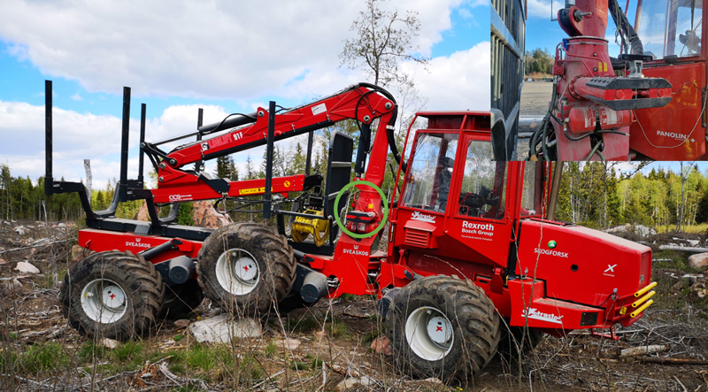
Fig. 1. The XT28 Forwarder and the mounting position of the stereo camera (green circle, close-up to the right).
2.2 Development of the log-grasping node and model training
A novel boom control node was developed using the information from the stereo camera and logic to send control signals to the boom (explained below). Fig. 2 summarises the control system logics in a flow chart, and examples of log grasping are shown in the Supplementary file S1.
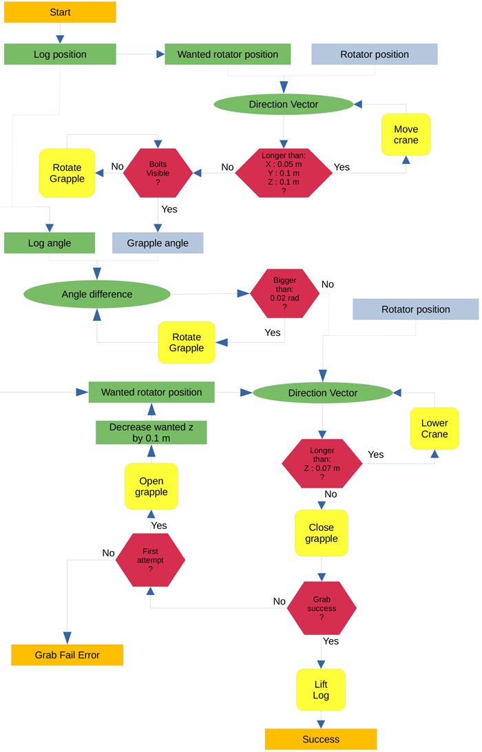
Fig. 2. Flow chart of the control system logic. Input and outputs are orange, detected objects (rectangles) or calculated targets (ovals) are green, terms are red, actual detected boom positions are grey, movement is yellow. A detected log and positioned rotator give a calculated movement vector.
To train the model, around 500 images were tagged with five objects: the two shank-bolts on the grapple, the rotator, the log end, the grapple, and the log (Fig. 3). Images were sampled over a year in different weather conditions and seasons. The tests were mainly carried out on a gravel-covered car park.
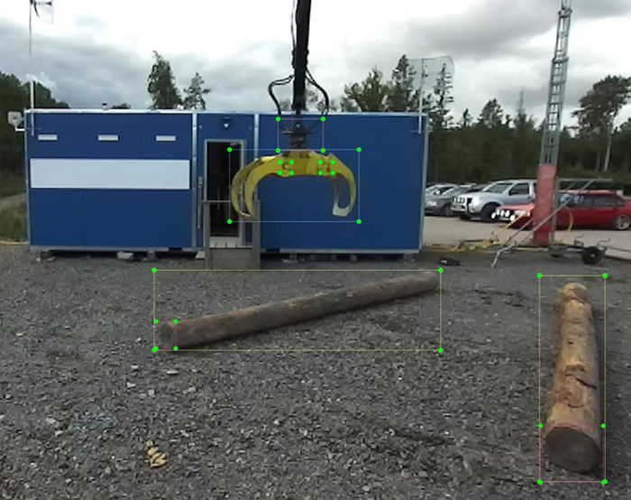
Fig. 3. Five objects, two shank-bolts on the grapple, the rotator, logs, and visible log ends were tagged in approximately 500 images to train object detection.
The system calculates the position of the log by determining the median value from 50 samples of the bounding-box centre obtained from the ZED-2 camera. Similarly, the median value from 50 samples of the bounding-box centre of the log-end is used to determine its position. If multiple objects are detected, the program chooses the log closest to the grapple and the log end closest to the log. The control node moves the rotator to 2 m above the desired target point (directly above the log position, Fig. 4), rotates the grapple so that the vector between the two shank-bolts is perpendicular (+/– 0.02 rad) to the vector between the log and the log end, then lowers the rotator to 0.95 m above the log and closes the grapple. If the program cannot detect the shank-bolts, it slowly rotates the grapple until both bolts are visible.
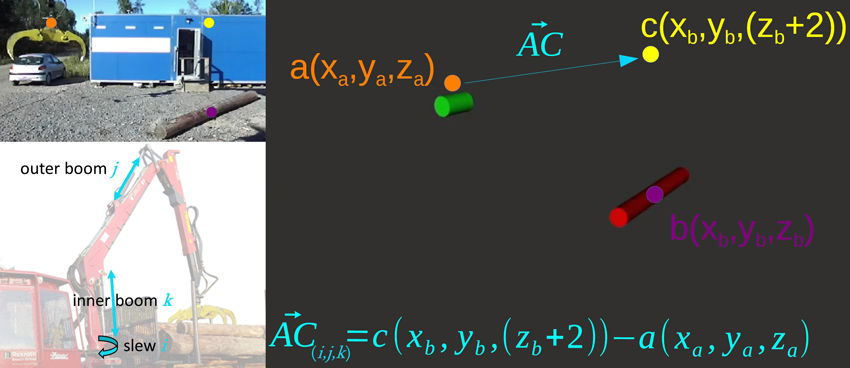
Fig. 4. The centre point of the rotator (a, orange), the log centre (b, purple), and the target position 2 m above the log (c, yellow). AC(i,j,k) is the vector of the boom movement based on the present position and used as control signals to the boom where component i goes to slew, component j goes to the outer boom and component k goes to the inner boom.
The control program gives input to the boom equivalent to that of a human operating the joysticks. The system assumes that the inner boom changes the height of the grapple (Z direction in the ZED camera coordinate system), the outer boom changes the distance to the grapple (Y direction), and the slew changes the distance sideways (X direction). Fig. 4 demonstrates how the vector (ACi,j,k) for boom movement between present position and the position above the log is calculated. The actual positions of the identified objects are of less importance as the rotator and log are seen in relation to each other and the direction of movement is given from their relative positions in the same coordinate system of the ZED-2 camera.
A proportional controller is used to obtain a smooth arrival at the target, where the distance between the object and desired boom-tip position is used for scaling the signals. A distance of over one metre generates 100% signal amplitude. From one metre, the signal is scaled down proportionally, with the distance in centimetres as a percentage of maximum signal amplitude.
To handle noise produced by the ZED camera, the control signal is smoothed by only allowing it to change the signal by 0.05 per cycle, acting as a simple low-pass filter. The total amplitude of the signal is –1 to 1.
In some situations, the rotator is hard to identify through image analysis. To make the controller more reliable when the rotator cannot be detected, the rotator position is calculated from the centre position between the shank-bolts by adding a fixed offset of 0.2 m to the side and 0.33 m in height. The accuracy of the calculated rotator position is in line with the noise of the camera, i.e., it is decided by the general precision of the method.
Log grasping will fail if the grapple is too high for the grapple shanks to reach beneath the log. This situation is detected by the camera: if the log end is not elevated at least 20 cm after the grapple has been closed, the system deems it as a failed attempt, opens the grapple and lowers the boom-tip to 85 cm over the log, then retries the pick-up. If the log end still does not move, the system sends a signal for failed pick-up and aborts the operation.
2.3 Experimental field test
2.3.1 Test 1
The purpose of Test 1 was to measure accuracy and precision/repeatability of the system. The grapple started from two different locations and reached a position directly above the log. The log used in the test was 4.87 m long, with end diameters of 0.34 m and 0.27 m. The tests were carried out with the small end closest to the machine. The weather was cloudy and humid with an air temperature of 3 °C. The ground was partly covered with snow.
The camera, the log, and the stationary part of the rotator were all measured with a GNSS-receiver (ArduSimple, ublox F9p) with RTK-correction from the Swedish Land Survey Authority (Lantmäteriet). During the test the GNSS-receiver was mounted on the rotator.
Three log angles (1 = 11°, 2 = 129° and 3 = 94°) were tested with the log centre (i.e., the boom-tip target point) remaining in the same position (Fig. 5). The test was repeated 10 times for each starting position and log angle, except for angles 2 and 3 where only 9 datapoints from start position 2 were recorded (n = 58). All positions were corrected for the offset (140 mm) of the rotator centre to the GNSS-antenna in the data analysis. For each log angle, the arithmetic mean value of all positions was calculated, and both the distance from the mean position to the log centre point and the shortest distance to the centreline of the log were calculated. The average distance from the mean point to each recorded point was also calculated.
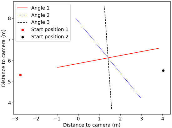
Fig. 5. Set up of Test 1 with start positions of the grapple (points) and different log angles (lines). The logs are placed in front of the camera on the left side of the machine. Angle 1 = 11°, Angle 2 = 129° and Angle 3 = 94°.
2.3.2 Test 2
The purpose of Test 2 was to establish the success rate of log grasping with the log placed in three different locations, with three different log angles at each location (Fig. 6). Angle A was 53°, 53°, and 43° for position 1, 2, and 3, respectively. Angle B was 92°, 88°, and 91° and angle C was 118°, 120° and 134° for position 1, 2 and 3, respectively. All angles are given counterclockwise from the positive x-axis in the coordinate systems of Figs. 5–9.
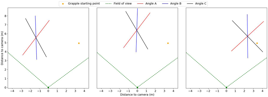
Fig. 6. The location and angles of the logs (lines) in relation to the camera view (green dotted lines). The orange dot shows the starting position of the grapple. View larger in new window/tab.
The weather during the day of Test 2 was sunny with a temperature of 3 °C, with the sun at a low angle, almost directly from the left in relation to the camera. The same log as in Test 1 was used.
The grapple was positioned at the starting position (orange dot, Fig. 6) and a command to pick up the log was given. Five attempts were made for each log position and angle (n = 45).
The criteria for a successful grasping were:
- Position: The centre of the grapple must be at least 25% from either of the log ends.
- Height: The grapple jaws should be closed under the log, not pinching the log with the tips. If the first try fails and the system detects it as a failure, one more attempt is allowed before the grasp is deemed a failure (as described above).
The camera, the log and log angles were all positioned with the same GNSS-receiver as in Test 1.
3 Results
3.1 Test 1
The recorded grasping positions are displayed in Figs. 7–9, and the mean distance from the final grapple position to the log centre in Table 1. Generally, the repeatability of finding the log centre was high, with an average distance for the different repetitions to the mean point of repetitions less than 10 cm (Table 1). However, the cluster of pick-up positions was slightly skewed to the side of the log, depending on the angle. The mean point of the trials was closest to the log centre for angle 1 and farthest away for angle 3 (Table 1, Figs. 6–8). All points, except one, lay within the jaws of the grapple (Fig. 9).
| Table 1. Results of Test 1 – repeatability. Number of trials (n) of movements from two different starting positions to estimated log centre when the log is placed in three different angles, distance (cm) from the arithmetic mean point of individual pick-up positions to log centre, standard deviation (STDAV (cm)), minimum/maximum distance from mean point to pick-up points (cm), and distance (cm) from the arithmetic mean point to log centreline. | |||||
| n | Mean point to log centre (cm) | STDAV (cm) | Min/Max distance from mean point (cm) | Mean point to log centreline (cm) | |
| Angle 1 (11°) | 20 | 24 | 7.3 | 2/16 | 21 |
| Angle 2 (129°) | 19 | 73 | 9.6 | 4/14 | 36 |
| Angle 3 (94°) | 19 | 83 | 8.5 | 3/42 | 16 |
| Angle 3 deviating point excluded | 18 | 84 | 6.6 | 3/15 | 18 |
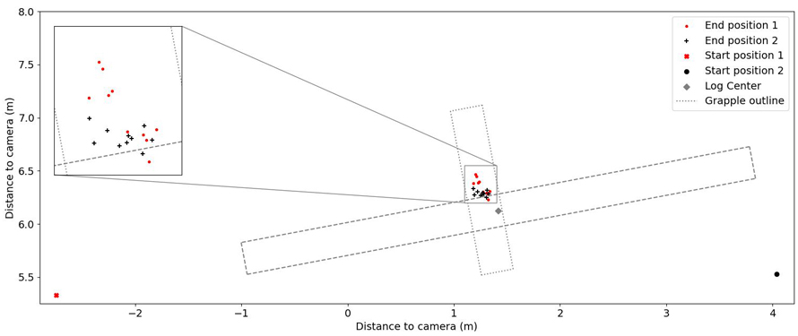
Fig. 7. Test 1, angle 1. Log and grapple positions. The axes show distance in metres to the camera. The starting positions are represented by large symbols and the end positions with small symbols. The log outline is represented by a dashed line. View larger in new window/tab.
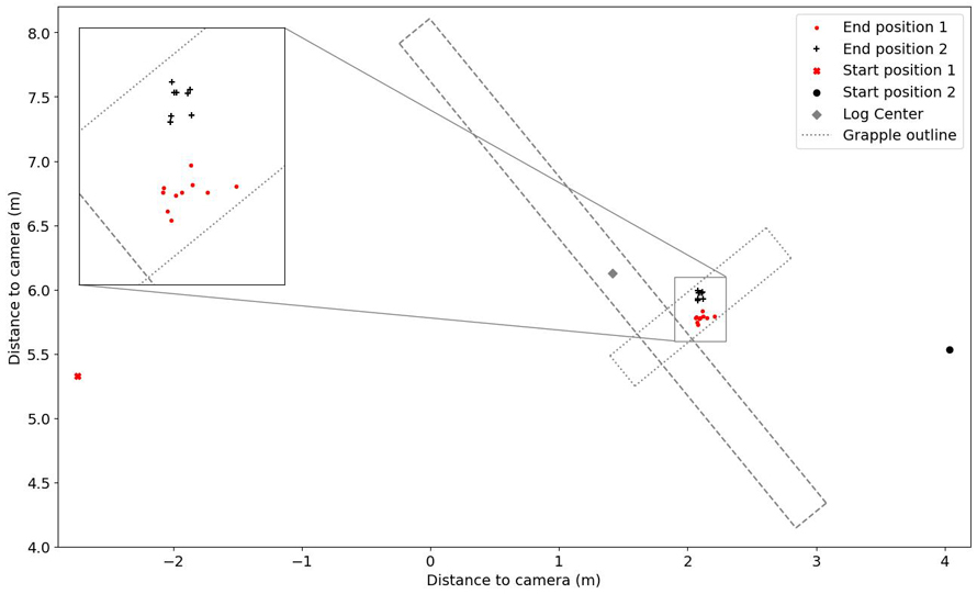
Fig. 8. Test 1, angle 2. Log and grapple positions. The axes show distance in metres to the camera. The starting positions are represented by large symbols and the end positions with small symbols. The log outline is represented by a dashed line. View larger in new window/tab.
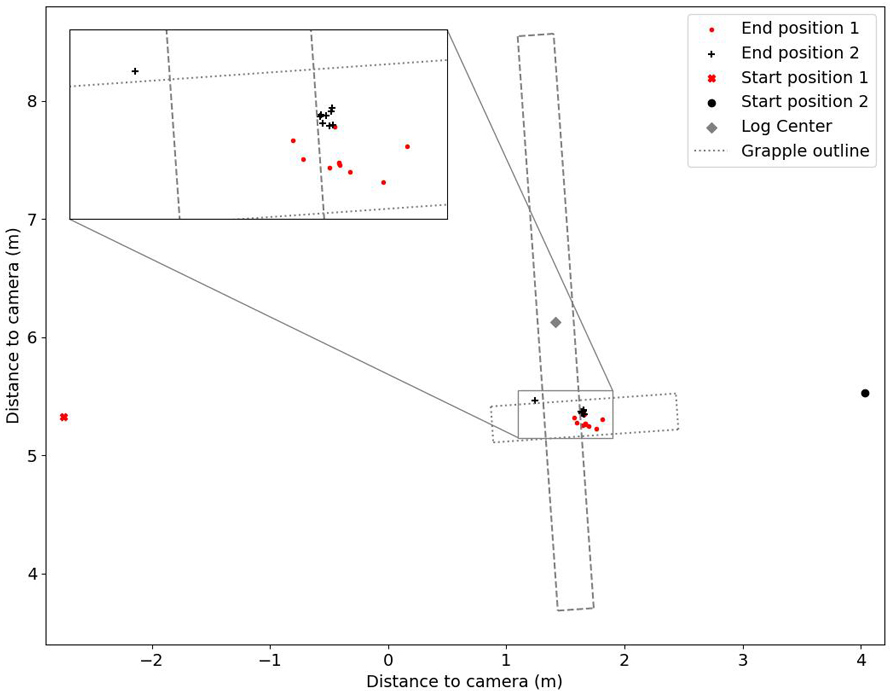
Fig. 9. Test 1, angle 3. Log and grapple positions. The axes show distance in metres to the camera. The starting positions are represented by large symbols and the end positions with small symbols. The log outline is represented by a dashed line.
3.2 Test 2
The system successfully grasped the logs in 37 of the 45 attempts, achieving a success rate of 82% (Table 2). Five of those succeeded at the first attempt and 32 at the second (Table 2). Failures during the initial attempt were attributed to various causes. Specifically, in two instances at position 1, angle A, the system failed to determine the log’s position, causing the grapple to move out of the camera’s field of view. After two consecutive failures, the program was restarted, successfully resolving the issue. The last attempt at position 1, angle B, also failed, as the grapple, although near the correct position above the log, did not meet the system’s criteria. The subsequent trial, the first attempt at position 1, angle C, also failed, leading to a system restart. All subsequent attempts were successful, except at position 3, angle C, where the system managed to pick up the log only once. On the unsuccessful attempts, the grapple was correctly positioned but continuously rotated without initiating the log pickup.
| Table 2. Results of Test 2 – pick-up success. The number of attempts that succeeded at first or second trials are presented, as well as the failures for each position and angle. Angle A was 53°, 53°, and 43° for position 1, 2, and 3, respectively. Angle B was 92°, 88°, and 91° and Angle C was 118°, 120° and 134° for position 1, 2 and 3, respectively. | |||||||||
| Angle A | Angle B | Angle C | |||||||
| Success 1st attempt | Success 2nd attempt | Failures | Success 1st attempt | Success 2nd attempt | Failures | Success 1st attempt | Success 2nd attempt | Failures | |
| Position 1 | 1 | 2 | 2 | 0 | 4 | 1 | 0 | 4 | 1 |
| Position 2 | 0 | 5 | 0 | 0 | 5 | 0 | 1 | 4 | 0 |
| Position 3 | 2 | 3 | 0 | 1 | 4 | 0 | 0 | 1 | 4 |
4 Discussion
The results indicate that one stereo camera may suffice for object recognition and grapple positioning to grasp logs autonomously with a full-scale forwarder. In 82% of the trials the system successfully identified and picked up the log (Table 2) and, in another 9%, the failures were solved by restarting the program, indicating other problems than the method itself. In the remaining failures (9%), the grapple was close to or at the position above the log, but the system was never satisfied with the position and the grapple was rotating. A limitation of the present system is when the grapple is rotated towards the camera centre-point. The system measures the grapple angle by detecting the bolts on the grapple and, when those cannot be detected, the system cannot measure the angle. This is what happened in Test 2, location 3, angle C. There are several possibilities to overcome this issue. A simple fix may be to look at the bounding box of the grapple and adjust the angle until the smallest width is reached. However, in real-life, the machine can be repositioned by driving forwards or backwards to avoid this situation. An easy way to increase the success rate of the first attempt is to set the reference height of the rotator 10 cm lower above the log directly (0.85 m instead of 0.95 m). However, this would also involve grasping a significant amount of gravel/soil, which is undesirable. Another option, applicable to a hard smooth surface as in the tests presented here, is to detect the log diameter at the log end and automatically adjust the reference height above the log in relation to the diameter of the log end. However, in real conditions on the soft forest ground with mosses, small bushes (Ericaceace spp.), and harvest residues, it is challenging to detect the entire log end, which might result in an incorrect reference height. On the other hand, an advantage of the soft organic layer is that the grapple can be positioned lower than on a hard surface without grasping mineral soil.
The system demonstrated high repeatability/precision, as shown in Test 1 (Table 1, Figs. 7–9). However, depending on the angle of the log towards the camera, the system estimates the log centre differently. The best estimate is for angle 1 (Table 1, Fig. 7). The system has more difficulties when the log is positioned with the end towards the camera, making the log look shorter than it is, resulting in a centre position estimate closer to the camera. If the logs are in an unfavourable position/angle, one possibility is to use a slower but more precise detection method for the initial measurement of the log to get a good position and angle, such as the semantic segmentation methods used by Fortin et al. (2022). The boom could then be moved to the desired position using the faster method in this article. Semantic segmentation is probably also better when it comes to grasping a pile of logs, instead of one at a time. As can be observed in Figs. 7–9, the target point identification seems to include a systematic offset, depending on the log angle. The offset, however, was too small to influence the success rate of log grasping. The reason for the skewed target identification is that the centre of the two-dimensional bounding box is used for calculating the three-dimensional target coordinate. When the log ends are at a different distance from the camera, the bounding-box centre will represent a point closer to the nearest log end. As the skewedness is systematic with high precision and repeatability, it is easy to adjust in future trials.
Fast object identification and positioning is key for the suggested method. A regular gaming laptop can run the detection and positioning at a speed of ~24 Hz, sufficiently fast to satisfy the machine’s minimum requirement for control signal frequency. This is also fast enough to compensate for the non-independent and non-linear control used. As an example, when the system wants the grapple to go straight in the Z direction it will send a signal to the inner boom. When the inner boom is changed, the grapple will also travel in the Y direction. That change is detected, and the system then sends a signal to change the outer boom to get the Y-value of the grapple back to the desired value.
The suggested method is simpler compared to the approaches used in previous studies, where the camera is used to position the log in the coordinate system of the boom (Gietler et al. 2022; Ayoub et al. 2023; Li and Lideskog 2023; La Hera et al. 2024). Since our study served as an initial test of a new method, we have not assessed the accuracy of YOLOv5 itself in determining the correct coordinates from image data. Others, such as Li and Lideskog (2021), have conducted evaluations on the precision of positioning stumps and stones in a clear-cut forest environment using a similar system. Their findings indicate that, within 1–10 m from the camera, objects could, on average, be positioned within 0.33 m of their true coordinates. In another study (Li and Lideskog 2023), they positioned logs with a 0.27 m mean error from its true location and angle mean error of less than 3°. An advantage of our suggested method is that the system identifies the relative position between the objects, not the absolute position relative to the camera. This makes the control less reliant on the accuracy of the camera and the absolute position of the camera relative to the boom given by the YOLO-model.
Today, most forwarders lack a sensor for the rotation of the grapple, which makes it impossible to operate the boom autonomously without retrofitting the boom with some kind of rotator angle sensor. The system used in this study could be mounted on almost any forwarder, and only needs calibration of the boom control signals.
A limitation of the suggested system is that it only uses three degrees of freedom for the boom. To utilise more degrees of freedom, i.e., the extension boom, a system with better knowledge about its parts from, for example, internal sensors must be used, or a boom with a more advanced control system, such as boom-tip control. The current control system relies only on system speed to adjust for motion errors. One way to make the control system smoother is to implement a self-learning control algorithm to give the system an ability to think ahead. A skilled operator works in this way, and moves multiple axes at once to get the desired movement of the grapple instead of only reacting to unwanted changes. A first step would be to prioritise motions in certain situations where the boom is likely to hit the ground with the current control strategy. Future work also includes expanding the image analysis training dataset, to enable the controller to identify the objects with higher precision. For this, open datasets, such as TimberSeg1 (Fortin et al. 2022), could be used as a complement.
The method also requires evaluation under various ambient light conditions and sun angles before conducting full operational tests. Additionally, it is essential to ensure that the method functions effectively in low-light or dark conditions, with support from the forwarder headlights.
Controlling robots with only cameras and interceptive sensors (cylinder pressures, positions, engine load, etc) is an interesting approach, as almost all the information used by an operator is available, and the cost of sensors is low. Other data from, e.g., LiDAR, radar, and ultrasound could sometimes be used to improve accuracy of the information, but then the information overlap needs to be managed.
The method described in this study could be a part of an automated system. One possible setup is that both the harvester and forwarder are equipped with RTK-GNSS receivers with very high accuracy and precision. The forwarder follows the route suggested by the decision support tool GoForward (Hansson et al. 2022), either manually, teleoperated, or by autonomous driving. The input data to GoForward comprises various kinds of geodata and the harvested production (hpr) files from the harvested site. It is important that v4.0 of StanForD2010 (2021) is implemented to ensure that log positions are given. Based on the GoForward route, the forwarder positions itself with the camera facing the logs to grasp. The log grasping is carried out as described in this study and when the log is lifted above the ground, the boom’s internal sensors are used to follow a programmed path to place the logs in the bunk. There are several different methods for placing the logs in the bunk autonomously (Westerberg 2014; La Hera et al. 2021). From the harvested production file, the system is aware of the number of logs spread out in a specific area. If multiple logs are visible in the same image, the system selects the one closest to the camera and can also indicate if multiple logs are observed on the ground. The loading cycle could be repeated until no more logs are visible. The system could then compare this information with the harvested production data for the same area to ensure that all logs within reach of the forwarder are loaded into the bunk. Then, the forwarder moves along the route proposed by the GoForward tool and repeats the log-grasping and loading. To prevent situations where the system comes to a standstill because logs that should be present are not recognized by the image system, the machine could prompt the operator to intervene. The operator could swiftly teleoperate the machine, identify the logs, and manoeuvre the grapple accordingly. This poses no issue if the majority of the logs are detected by the system, and the operator can monitor multiple machines simultaneously.
To conclude, this study presents simple target-point detection and log grasping in real time using only one stereo camera. The sturdiness of the method is ensured through the simple feedback system based on positioning both the log and the grapple with the same camera so that no calibration or sensor fusion is needed. The presented system provides a method for achieving automated boom-tip control with a standard boom, designed without boom-tip control. The log grasping was successful when tested on a full-sized forwarder in real time, but needs to be adjusted to grasp more than one log at a time. The method may become part of an autonomous forwarding system or could provide operator support in semi-autonomised systems.
Declaration of openness of research materials, data, and code
The code developed in this project may be accessible on request, depending on the intended use.
Authors’ contributions
TS: Conceptualisation, Data acquisition, Interpretation of results, Writing – original draft.
AN: Data acquisition, Interpretation of results, Writing – original draft.
RB: Supervision, Interpretation of results, Writing – original draft.
LH: Supervision, Interpretation of results, Writing – original draft.
Acknowledgements
We would like to thank Leslie Walke for language editing.
Funding
This study was funded by Vinnova through the challenge-driven innovation project: Autonomous forest regeneration for a sustainable bioeconomy (Autoplant). Grant number: 2020-04202.
References
Abdelsalam A, Happonen A, Kärhä K, Kapitonov A, Porras J (2022) Toward autonomous vehicles and machinery in mill yards of the forest industry: technologies and proposals for autonomous vehicle operations. IEEE Access 10: 88234–88250. https://doi.org/10.1109/access.2022.3199691.
Andersson J, Bodin K, Lindmark D, Servin M, Wallin E (2021) Reinforcement learning control of a forestry crane manipulator. Proceedings of the IEEE/RSJ International Conference on Intelligent Robots and Systems (IROS), Prague, Czech Republic, pp 2121–2126. https://doi.org/10.1109/IROS51168.2021.9636219.
Ayoub E, Levesque P, Sharf I (2023) Grasp planning with cnn for log-loading forestry machine. Proceedings of the IEEE International Conference on Robotics and Automation (ICRA), London, United Kingdom, pp 11802–11808. https://doi.org/10.1109/ICRA48891.2023.10161562.
Dell’ Amico A, Ericson L, Henriksen F, Krus P (2015) Modelling and experimental verification of a secondary controlled six-wheel pendulum arm forwarder. Proceedings of the 13th ISTVS European Conference, Rome, October 21–23, 2015. http://urn.kb.se/resolve?urn=urn:nbn:se:liu:diva-122390.
Fortin J-M, Gamache O, Grondin V, Pomerleau F, Giguère P (2022) Instance segmentation for autonomous log grasping in forestry operations. Proceedings of the IEEE/RSJ International Conference on Intelligent Robots and Systems (IROS), Kyoto, Japan, pp 6064–6071.https://doi.org/10.1109/IROS47612.2022.9982286.
Gelin O, Björheden R (2020) Concept evaluations of three novel forwarders for gentler forest operations. J Terramechanics 90: 49–57. https://doi.org/10.1016/j.jterra.2020.04.002.
Gelin O, Henriksen F, Volungholen R, Björheden R (2020) Improved operator comfort and off-road capability through pendulum arm technology. J Terramechanics 90: 41–48. https://doi.org/10.1016/j.jterra.2020.01.003.
Gelin O, Rossander M, Semberg T, Englund M, Andersson M, et al. (2021) Automation för autonom terrängmobilitet (auto2). Slutrapport – steg 2. [Automation for autonomous terrain mobility (auto2) final report – stage 2]. Arbetsrapport 1077-2021, Skogforsk, Uppsala.
Gietler H, Bohm C, Ainetter S, Schoffmann C, Fraundorfer F, Weiss S, Zangl H (2022) Forestry crane automation using learning-based visual grasping point prediction. Proceedings of the 2022 IEEE Sensors Applications Symposium (SAS), Sundsvall, Sweden. https://doi.org/10.1109/SAS54819.2022.9881370.
Hallonborg U (1997) Ingen man på maskinen − en förarlös vision. [no man on the machine – a autonomous vision]. [Work report of the Forestry Research Institute of Sweden]. Arbetsrapport 399, Skogforsk, Uppsala.
Hansson L, Andersson K, Andersson H, Persson T, Englund M, Jönsson P (2021) Utformning av operatörsstationer för fjärrstyrning inom jord- och skogsbruk. [Design of control stations for teleoperation in agriculture and forestry]. Arbetsrapport 1094-2021, Skogforsk, Uppsala.
Hansson LJ, Forsmark V, Flisberg P, Rönnqvist M, Mörk A, Jönsson P (2022) A decision support tool for forwarding operations with sequence-dependent loading. Can J Forest Res 52: 1–14. https://doi.org/10.1139/cjfr-2022-0011.
Hellström T, Lärkeryd P, Nordfjell T, Ringdahl O (2009) Autonomous forest vehicles: historic, envisioned, and state-of-the-art. Int J For Eng 20: 31–38. https://doi.org/10.1080/14942119.2009.10702573.
La Hera P, Morales DO, Mendoza-Trejo O (2021) A study case of dynamic motion primitives as a motion planning method to automate the work of forestry cranes. Comput Electron Agric 183, article id 106037. https://doi.org/10.1016/j.compag.2021.106037.
La Hera P, Trejo OM, Lindroos O, Lindbäck T, Latif S, Li S, Karlberg M (2024) Exploring the feasibility of autonomous forestry operations: results from the first experimental unmanned machine. J Field Robot. https://doi.org/10.1002/rob.22300.
Li S, Lideskog H (2021) Implementation of a system for real-time detection and localization of terrain objects on harvested forest land. Forests 12, article id 1142. https://doi.org/10.3390/f12091142.
Li S, Lideskog H (2023) Realization of autonomous detection, positioning and angle estimation of harvested logs. Croat J For Eng 44: 369–383. https://doi.org/10.5552/crojfe.2023.2056.
Lindroos O, La Hera P, Häggström C (2017) Drivers of advances in mechanized timber harvesting – a selective review of technological innovation. Croat J For Eng 38: 243–258. https://crojfe.com/site/assets/files/4084/lindroos.pdf.
Lindroos O, Mendoza-Trejo O, La Hera P, Ortiz Morales D (2019). Advances in using robots in forestry operations. In: Billingsley J (eds) Robotics and automation for improving agriculture. Burleigh Dodds Science Publishing, pp 233–260. https://doi.org/10.19103/AS.2019.0056.18.
Lundbäck M (2022) Roadmap for teleoperation and automation of forwarding. Doctoral thesis. Acta Univ Agric Suec 2022:29. Swedish University of Agricultural Sciences, Umeå. https://res.slu.se/id/publ/116658.
Noordermeer L, Sørngård E, Astrup R, Næsset E, Gobakken T (2021) Coupling a differential global navigation satellite system to a cut-to-length harvester operating system enables precise positioning of harvested trees. Int J For Eng 32: 119–127. https://doi.org/10.1080/14942119.2021.1899686.
Ringdahl O (2011) Automation in forestry: development of unmanned forwarders. Doctoral thesis. Umeå Universitet, Umeå. https://urn.kb.se/resolve?urn=urn%3Anbn%3Ase%3Aumu%3Adiva-43265.
StanForD2010 (2021) Stanford 2010 - modern communication with forest machines. Skogforsk, Uppsala.
Stanford Artificial Intelligence Laboratory et al. (2018) Robotic operating system. https://www.ros.org.
Visser R, Obi OF (2021) Automation and robotics in forest harvesting operations. Croat J For Eng 42: 13–24. https://doi.org/10.5552/crojfe.2021.739.
Wallin E, Wiberg V, Servin M (2024) Multi-log grasping using reinforcement learning and virtual visual servoing. Robotics 13, article id 3. https://doi.org/10.3390/robotics13010003.
Weiss S, Ainetter S, Arneitz F, Perez DA, Dhakate R, Fraundorfer F, Gietler H, Gubensak W, Ferreira M, Stetco C (2020). Automated log ordering through robotic grasper. Proceedings of the Austrianthe Austrian Computer Vision and Robotics Workshop 2020. Graz University of Technology, Graz, Austria, pp 50–53. https://austria-forum.org/web-books/en/jacv00en2020isds/000066.
Westerberg S (2014) Semi-automating forestry machines: motion planning, system integration, and human-machine interaction. Doctoral thesis. Umeå Universitet, Umeå. http://urn.kb.se/resolve?urn=urn:nbn:se:umu:diva-89067.
Total of 28 references.
Send to email
